
🤖 Understanding The ROS Robot Stack
There are many aspects to designing robot software. ROS uses some best practices and design strategies to allow developers to quickly create high-quality robot software. Some of these design details are not explicitly covered by the ROS tutorials and some are guided by community and industry knowledge and practice and are not directly addressed in the ROS core framework. As a result, it can be difficult to understand how to use ROS in a professional project when first starting out.
Instructions
There are some steps to follow in order to get the best out of the ROS framework:
- Create CAD models of your robot and world, and import these into the ROS environment using URDF and SRDF formats
- Create low-ROS-dependency hardware drivers for every piece of computer-controlled hardware (cameras, motors, lasers, etc.)
- Create a ros_control/ros_controller model for your robot
- Use the ‘overlays’ approach to build a ‘robotics stack’ for your robot
The Benefits
By following this process, the robotics software that is produced will be testable, maintainable, easy for others to follow and adopt, and allow for full access to rich ROS features.
Overlays
The overlay approach refers to the idea of creating layers of software where each layer in a stack inherits and extends features from the previous layer. In ROS this approach can be used to develop a complex robot by adding layers of complexity in smaller software layers. Each layer inherits functions from the previous layers. The diagram below illustrates the widely accepted robotics stack for a ROS-based robot software system.
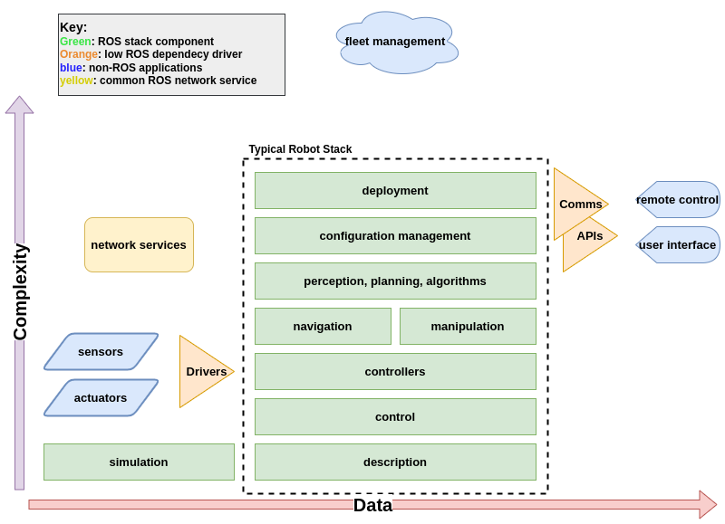
Robot Description
The robot description is a declaration of the characteristics of a particular robot. This includes the robot geometry, mechanisms, and frames of reference. Robot linkages, joints, mechanical, control, simulation, and sensor parameters are declared in a robot description. Robot components that cannot be declared are described by dynamic components such as reference frames for odometry and maps - which are dynamically published by localisation and mapping algorithms.
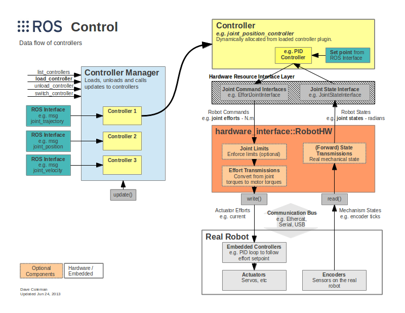
ROS Control/Controller
ROS control is an architectural paradigm that provides an abstraction for controlling a robot. This abstraction allows software overlays such as navigation and manipulation to operate in a consistent manner across a wide variety of different robotic mechanisms and configurations. Below is the design diagram for ROS control.
Network Services
In any ROS network, there are common services that are broadly useful. This may include services such as transform lookup, parameter configuration, resource discovery, visualization, introspection, and logging.
Drivers
Drivers interact with specialised or dedicated hardware or real-world interfaces. These may include cameras, lasers, buttons, radios, motors, actuators, encoders, etc. The control and management of these robotic components can be complex and specialised with specific implementation requirements. ROS does not define specific requirements for all devices. As such, it is better to design software for these components that use the best practice for the particular application. ROS is then used as a communication wrapper to translate the necessary data and communications into the ROS network. By providing a translation layer, the specificity of the hardware can be abstracted and common ROS tools can interact with a wide variety of hardware with greater interoperability. The mechanism for designing drivers often follows the below pattern:
- Create a hardware communications library using C++ or another low-level language, that manages all aspects and features provided by the hardware - with an accessible API.
- Create a wrapper API using ROS primitives such as message types, topics, and services that translate the hardware library API into a ROS network.
- Use shared memory interfaces and state machine models to manage real-time requirements of the hardware within the context of a ROS node (computer process) or ‘nodelets’ (computer threads)
Simulation
Following similar patterns seen in software development, simulation can be considered the ‘staging’ environment for robotics software. The goal of creating a simulation for a ROS-based robot is to match the expected real-world behaviour of the robot as closely as possible. In other words, making the development environment as close to the production environment as possible. This improves the testing and delivery of software. An extra challenge in robotics software development is the inherent costs associated with failure in the real-world context with potentially disastrous outcomes. As such, it is important to spend considerable effort in testing software in simulation BEFORE testing on real hardware.
Test to prevent disaster!
Always verify designs in rigourous testing environments before transitioning to the real world.
A design goal for the ROS robotics stack is to make most (if not all) components of the stack operate in the exact same manner in a simulation environment as they would in a real deployment.
Some software components will not run in the simulation environment. Some examples include drivers and ros_control. These components must often be simulated. In some cases, simulation in the loop (SITL) is used to include these element in simulation as well.